RoboDog · Volume 11
Synthesis & the Build Roadmap
Eleven volumes of Phase 1 research converge here. Vols 1–4 established the vocabulary — what quadruped locomotion demands, what the commercial and open-source ecosystem provides, and how the component classes (actuators, compute, sensors, power) translate into building-block decisions. Vols 5–7 resolved those decisions into three concrete, costed, buildable tiers, each with a honest accounting of capability and limits. Vols 8–10 traced the cross-cutting systems — autonomy software, the payload back, power and weatherproofing — that span the tiers and escalate with them. This final volume synthesizes those findings into a per-tier scorecard, a feasibility-wall map, a dependency graph, buy-versus-make guidance, a risk register, and the explicit handoff to Phase 2 Fusion 360 CAD and PCB design.
11.1 The Ladder as a Learning Path
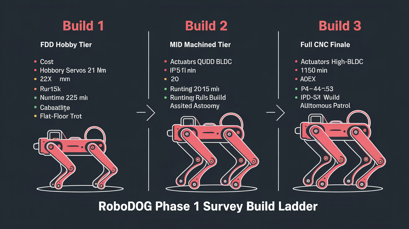
The three-build ladder is not a spectrum of alternatives from which one tier is chosen. It is a sequential program: Build 1 is built first, its lessons cataloged, and those lessons used to de-risk Build 2; Build 2 validates the hardest engineering problem in the program — dynamic QDD locomotion — before the owner commits to the Build 3 bill of materials. Vol 1 frames this as the program’s foundational design decision, and every subsequent volume reinforces it. [1]
The rationale is pedagogical as much as financial. A builder who has not experienced how servo stall torque degrades under thermal derating will not calibrate the safety factors in a QDD torque budget with appropriate conservatism. A builder who has not watched a PID gait loop go unstable on physical hardware — not in simulation — will not design the real-time MCU separation that Build 2 requires. The ladder is structured so that each tier forces the builder through the specific failure mode that the next tier’s design must prevent.
Vol 3’s commercial landscape establishes the capability target: Boston Dynamics Spot (IP54, −20°C to +55°C, 90-minute runtime, 14 kg payload) is the commercial benchmark the program aspires toward. [2] The Unitree B2 (IP67, 60 kg, 40 kg payload, 4+ hours runtime) and DEEP Robotics X30 Pro (IP67, ≥4 m/s) define the industrial ceiling. [2] Build 3 targets a similar envelope at Labrador scale using a machinist’s skill set and open-source software in place of a corporate supply chain.
Vol 4’s component survey makes clear that the actuator choice is the pivotal decision at every tier. [3] Commercial platforms that achieve reliable outdoor operation (Spot, B2, X30) all use proprietary but clearly QDD-inspired or harmonic-drive actuators. Open-source platforms that achieve dynamic gaits use QDD. Platforms that use hobby servos walk indoors on flat surfaces. The ladder respects this constraint: it starts with hobby servos to learn the lesson cheaply, then steps to QDD for every build that actually matters to the mission.
11.2 Per-Tier Scorecard
The following scorecard distills the cost, capability, builder effort, and educational yield of each build tier from the figures established in Vols 5–7 and verified against the dossier for this volume.
Table 1 — Per-Tier Scorecard
| Attribute | Build 1 — FDM Hobby | Build 2 — Mid Machined | Build 3 — Full CNC |
|---|---|---|---|
| BOM cost (baseline) | ~$540 [4] | $8,775.52 [5] | $21,029.80 [6] |
| BOM band | $500–$590 [4] | ~$8,800–$10,000 [5] | ~$21,000–$22,500 [6] |
| Primary actuator | DS3218MG hobby servo, 2.11 N·m at 6.8 V [4] | CubeMars AK80-9 V3.0, 22 N·m peak, 9 N·m rated [5] | CubeMars AK80-64 KV80, 120 N·m peak, 48 N·m rated [6] |
| Required joint torque (design SF) | 1.77 N·m at SF = 2 (M = 1.5 kg, L = 0.12 m) — DS3218MG passes at 2.4× [4] | 14.72 N·m at SF = 2 (M = 10 kg, L = 0.15 m) — AK80-9 passes at peak (1.49×) [5] | 73.5 N·m at SF = 2.5, stair climb (M = 30 kg, L = 0.20 m, N = 2) — AK80-64 passes at 1.63× [6] |
| Actuator protocol | PWM (50 Hz) | CAN-FD, MIT protocol | CAN-FD, MIT protocol |
| Machine mass | ~1.5 kg [4] | ~10 kg [5] | ~30 kg [6] |
| Compute | Raspberry Pi 5, 8 GB | Jetson Orin NX 16GB, 100 TOPS | Jetson AGX Orin 64GB, 275 TOPS |
| Battery | 3S LiPo 2,200 mAh, 24.4 Wh [4] | 12S LiPo 10,000 mAh, 444 Wh [5] | 12S LiPo 20,000 mAh, 888 Wh [6] |
| Runtime (active) | 20–35 min [4] | See known open item [5][9] | 44–53 min [6][9] |
| IP rating | None (indoor only) [4] | IP5X enclosure only [5] | IP67 full build (target) [6] |
| Cold-weather | Not applicable | −10°C min (no active management) [5] | −20°C rated; PTC heater [6] |
| Terrain capability | Flat dry indoor floor | Outdoor hardscape; light drizzle | Stairs, slopes, all-weather, snow [6] |
| Autonomy level | Bluetooth gamepad teleop | Assisted (Nav2 + OAK-D Pro VPU) [7] | Full autonomous patrol + auto-dock [7] |
| Estimated builder-hours | 25–50 h [4] | 100–200 h (est.) | 400–600 h (est.) |
| What it teaches | IK calibration, gait loops, power sequencing, wiring fatigue management [4] | QDD torque sensing, real-time MCU separation, Nav2 integration, CAN-FD topology [5] | IP67 sealing protocol, full autonomy stack, RTK GPS, thermal management, cold-weather LiPo handling [6] |
Builder-hours for Builds 2–3 are synthesis estimates; no prior volume establishes a figure (Vol 5 gives Build 1’s 25–50 h).
Known open item — Build 2 runtime: Vol 6’s battery section states “90–120 min of active patrol” based on the Vol 4 Tier-2 planning budget of approximately 180–340 W average system draw. [5] Vol 10 applies an analogous methodology to Build 2 but uses a higher average joint-loading assumption derived from the AK80-9’s actuator data, arriving at approximately 25–30 min (est.). [9] This is a genuine ~3–4× spread that only instrumented hardware telemetry can resolve; the true Build 2 runtime depends on the actual average joint current under a specific gait and terrain load from the running prototype. (Note: Vol 6’s power-rail section gives a stance-phase peak of 2.2–3.6 kW across the legs simultaneously in stance — the figure that sizes traction-rail wiring, fusing, and connectors — which is not the time-averaged runtime draw and is therefore not part of this discrepancy.) The scorecard intentionally flags this open item rather than silently selecting one estimate; it is the first deliverable that Phase 2 hardware testing will resolve.
11.3 Where Each Tier Hits the Wall vs. the All-Weather Autonomous Mission
Each tier is honest about where it stops. These are not deficiencies to manage around — they are the data points that define the next tier’s design brief.
11.3.1 Build 1 Walls
Thermal / materials. PLA-CF, the structural filament specified for Build 1, has a glass-transition temperature of approximately 55–60°C. [4] A sunny summer day on concrete will soften structural leg members. The machine is explicitly indoor-only.
Moisture. None of the electronics is rated for moisture ingress. Rain will corrode servo PCBs and short PCA9685 traces. [4]
Torque and terrain. The DS3218MG servo has no backdrivability. An unexpected step edge loads the tibia as a lever and strips the gear train or falls over. The design envelope is flat, dry, indoor floor. [4]
Control architecture. Above 4 Hz gait frequency, ROS 2 jitter on the Pi 5 manifests as a stumbling stride. There is no real-time substrate. [4]
Runtime. Twenty to thirty-five minutes of active gait is insufficient for any sustained patrol cycle. [4]
Conclusion for Build 1: this tier cannot approach the all-weather autonomous patrol mission on any axis. It succeeds on its stated goal — building competence — and on nothing else. That is the correct design.
11.3.2 Build 2 Walls
IP sealing. The IP5X electronics enclosure provides dust protection and splash resistance but not immersion protection. The AK80-9 V3.0 actuator cable exits are not potted in the base configuration. Sustained rain will eventually ingress the enclosure. [5]
Stairs and rough terrain. Build 2 is sized for flat hardscape. The AK80-9’s 22 N·m peak is adequate for a 10 kg machine on a flat surface but does not provide the 73.5 N·m stair-climbing margin required for Build 3’s 30 kg frame at SF = 2.5. [5][6]
Autonomous operation. Build 2’s “assisted autonomy” requires an operator to initiate patrol sessions, monitor the run, and intervene on unexpected events. Full unsupervised scheduling is a Build 3 feature. [5]
Cold-weather. The Build 2 design does not specify cold-weather battery management, actuator lubricant considerations, or a heated battery bay. [5][9]
Runtime uncertainty. As noted in the scorecard, the Build 2 runtime is unresolved until instrumented measurements exist from the physical prototype.
Conclusion for Build 2: this tier closes the dynamic gait gap — the hardest engineering problem on the ladder — and validates that the owner can build, tune, and operate a QDD platform. It does not complete the patrol mission.
11.3.3 Build 3 Walls (Residual Risks)
Build 3 is designed to close the gap to the patrol mission. Its documented residual limits are:
Actuator sealing is builder-responsibility. The AK80-64 carries no published IP rating. Every element of the IP67 strategy — potting, cover plates, cable glands — is builder-implemented. [6] Inadequate potting at a single cable exit defeats the IP67 claim at that joint.
LiDAR cost is significantly higher than earlier estimates. The Livox Mid-360 at $4,275 (US distributor price confirmed in Vol 7 [6]) is approximately 5.7× the ~$749 figure cited in Vol 4 from the official livoxtech.com listing. [3] Builders planning from Vol 4 estimates must rebase their budget.
Cold-weather runtime is compressed. At −20°C with the PTC heater maintaining battery surface temperature, patrol runtime decreases to 35–41 minutes. [6][9] Combined with elevated actuator current draw in cold lubricant, the 20% SOC return threshold should be raised to 25–30% for sub-zero operation. [6]
Battery IATA restrictions apply. The 12S 20,000 mAh pack at 888 Wh exceeds the 300 Wh threshold above which IATA/ICAO restrictions apply to air freight. [6]
Geofencing and safety stops require explicit commissioning. The unsupervised patrol software must implement GPS-bounded geofences, person-detection safety stops, and a failsafe return on any unhandled exception before any unattended patrol session. [6]
11.4 Dependency Map
Each tier unlocks specific skills, tools, and validated assumptions that the tier above requires.
11.4.1 What Build 1 Unlocks for Build 2
Skills unlocked:
- Inverse kinematics calibration at the bench: URDF parameter tuning against a physical leg that falls over when the math is wrong [4]
- Gait loop instability recognition: direct experience with PID divergence above 4 Hz on a shared-compute architecture [4]
- ROS 2 / CHAMP software stack familiarity: node graph, hardware abstraction layer, Gazebo simulation workflow [4]
- Power rail sequencing: build 1 teaches the inrush-during-boot failure that motivates Build 2’s soft-start relay [4]
- Wiring fatigue: external servo leads across flexing joints fail within hundreds of cycles, motivating Build 2’s hollow-link cable routing [4]
Tools validated:
- Gazebo simulation-before-hardware workflow
- TrotBot / SpotMicroAI build log knowledge base
- FDM printer calibration for structural parts
Assumptions confirmed:
- The CHAMP / ROS 2 software architecture carries forward to Build 2 with only a hardware interface change (PCA9685 PWM → CAN-FD via micro-ROS)
- Per-unit URDF calibration is required; generic parameter files do not produce a level stance
11.4.2 What Build 2 Unlocks for Build 3
Skills unlocked:
- QDD actuator commissioning: CAN-FD node ID assignment, MIT protocol torque and position commands, joint state telemetry [5]
- Real-time MCU architecture: STM32G4 micro-ROS substrate, CAN-FD bus topology, gait control latency management [5]
- Nav2 integration: costmap layers, DWB local planner tuning, waypoint follower commissioning [5][7]
- Mixed-material machining: 6061-T6 shoulder brackets + PETG-CF link members, bearing press-fit tolerances [5]
- CAN bus fault diagnosis: node drop-off, timing issues on a 12-node bus [5]
Tools validated:
- The owner’s CNC mill against AK80-9 mounting hole patterns (Ø98 mm face, four M4 on 70 mm bolt circle)
- 12S LiPo balance charging procedures
- IP5X enclosure thermal performance at 25 W compute load
Assumptions confirmed:
- The AK80-9’s 22 N·m peak is adequate for a 10 kg frame at SF = 2 [5]
- Jetson Orin NX 16GB at 100 TOPS handles simultaneous CHAMP gait control and Nav2 path planning [5]
- The soft-start relay architecture eliminates boot-sequence voltage sag [5]
11.5 Buy-vs-Make-First Guidance
The owner’s full machine shop (CNC mill and lathe) and FDM printing capability changes the economic calculus at each tier compared to a builder without machining access. The guidance below is specific to that context.
11.5.1 Buy at Every Tier
Actuators. DIY QDD construction (naked outrunner + planetary gearbox + separate FOC controller + encoder) provides no cost advantage over the integrated AK-series modules and adds many additional failure modes competing for debugging time. [5] The AK80-9 at $479.90 and AK80-64 at $889.90 are the correct procurement choices.
Compute modules. Raspberry Pi 5, Jetson Orin NX, and Jetson AGX Orin are not reducible to DIY alternatives without abandoning ROS 2 compatibility and community support. Buy the recommended module at each tier.
Depth cameras and LiDAR. The Luxonis OAK-D Pro integrates a 4 TOPS VPU that offloads vision inference from the compute module. The Livox Mid-360 is available from one practical source at $4,275. Neither has a comparable DIY substitute. [6]
LiPo packs. Balance-charging a DIY pack from raw pouch cells is a fire risk without BMS expertise. Buy Tattu / Gens Ace packs with integrated protection circuits.
Sealed ABEC-5 bearings, stainless fasteners. Commodity items; buy in bulk.
11.5.2 Make at Build 2 and Build 3 (CNC Mill)
Shoulder side plates, hip pivot blocks. These are the highest-stress structural interfaces — 22 N·m at Build 2, 120 N·m at Build 3. Machining them from 6061-T6 (Build 2) or 7075-T6 (Build 3) billet on the owner’s mill is the correct fabrication path and the primary reason the build program requires a machine shop. [5][6]
Spine structural rails. The payload spine (30×40 mm rectangular tube sections with M6 boss grid on 50 mm centers) is designed for CNC drilling and tapping from extrusion stock. [6]
IP67 electronics enclosure. The sealed 6061-T6 enclosure with O-ring-seated lid requires precision bore for the O-ring groove — a straightforward lathe operation. [6]
Femur and tibia link members (Build 3). At 120 N·m joint torque, hollow rectangular-section aluminum links with cable bores are machined, not printed. [6]
11.5.3 Make (FDM) at Build 1 and as Complement at Build 2
Build 1 frame. The entire Build 1 structural body is FDM PLA-CF from SpotMicro STL files. This is deliberate — the frame is designed to be replaced, not endure. [4]
Build 2 link members and covers. PETG-CF upper and lower leg links (femur/tibia), electronics enclosure covers, wiring strain-relief clips, and foot pads are printed at Build 2. The machined members handle the highest-stress interfaces; printed parts handle lower-stress links and covers. [5]
11.5.4 Buy First, Then Make
The recommended sequencing is to buy all actuators before beginning any machining. Lead times for AK-series modules from CubeMars have historically ranged 8–12 weeks. [6] Every machined structural dimension depends on the actuator housing geometry (Ø98 mm face diameter and mounting bolt circle are the primary references). Ordering actuators first and beginning the Fusion 360 frame design with physical units in hand eliminates the risk of machining to nominal datasheet tolerances that differ from the actual received units.
11.6 Risk Register
The following register consolidates risks identified across Vols 5–7 and the cross-volume synthesis above. Likelihood and impact are assessed on a three-point scale: Low / Medium / High.
Table 2 — Risk Register
| # | Risk | Likelihood | Impact | Mitigation | Source vol |
|---|---|---|---|---|---|
| R1 | Build 2 runtime uncertain — ~3–4× spread between Vol 6 battery-section estimate (~90–120 min from ~180–340 W average draw) and Vol 10 scaled estimate (~25–30 min from higher loading assumption); true value requires hardware measurement | High | Medium | Instrument BMS current telemetry from first powered run; treat 25–30 min as conservative planning floor until prototype measurement resolves the spread | Vol 6 [5], Vol 10 [9] |
| R2 | AK80-9 / AK80-64 lead time 8–12 weeks delays build sequencing | High | High | Order actuators as first procurement action; do not begin machining until units arrive and bore diameters verified | Vol 7 [6] |
| R3 | Livox Mid-360 US price at $4,275 — 5.7× Vol 4 estimate | Confirmed | High | Baseline all budgets to $4,275; verify at point of purchase; lower-cost alternative (RPLIDAR S3 3D, ~$550 est.) exists at reduced point-cloud density | Vol 7 [6], Vol 4 [3] |
| R4 | Build 3 actuator sealing (IP67) fully builder-implemented | High | High | Pressure-test each potted actuator with a 2 m water column before first wet patrol; allow 24 h cure time for Dow Corning 3145 RTV | Vol 7 [6] |
| R5 | Cold-weather patrol runtime compressed to 35–41 min at −20°C | Medium | Medium | Raise auto-dock return threshold to 25–30% SOC for sub-zero operation; pre-heat battery to ≥10°C before enabling traction rail | Vol 7 [6], Vol 10 [9] |
| R6 | 888 Wh Build 3 battery exceeds IATA 300 Wh air-freight limit | Medium | Low | Ground shipment within the US is unrestricted; flag for any international procurement | Vol 7 [6] |
| R7 | RTK GPS correction stream lost (internet outage / NTRIP caster down) | Medium | Medium | System falls back to standard GPS at 1–3 m; waypoint navigation continues at reduced fidelity; local base station option (~$1,900 additional) provides independence | Vol 7 [6] |
| R8 | Build 3 unsupervised patrol unsafe without geofencing and safety stops | High | High | Commission GPS geofence, 2 m person-detection safety stop, and failsafe return-to-dock before first unattended session | Vol 7 [6] |
| R9 | AK80-64 64:1 gear ratio reduces backdrivability vs. AK80-9 | Medium | Medium | Design for controlled-speed patrol, not athletic bounding; 73.5 N·m design target at SF = 2.5 accommodates stair climbing without dynamic impact absorption | Vol 7 [6] |
| R10 | PETG-CF link member cross-layer tensile strength (32.9 MPa) lower than in-plane (51.3 MPa) | Medium | Medium | Print link members with rectilinear infill, full perimeters; orient primary load axis in-plane; replace printed links with machined aluminum at Build 3 | Vol 6 [5] |
| R11 | Jetson AGX Orin 64GB sealed-enclosure thermal management | Low | Medium | Use conduction-cooling cold plate at 50 W TDP; at 60 W sustained, thermal pad from cold plate to spine aluminum may be required | Vol 10 [9] |
11.7 The Phase-2 Handoff
Phase 2 is the transition from survey to design and fabrication. The survey (Phase 1) has established what to build, with which components, at what cost, and in what sequence. Phase 2 produces the original deliverables: Fusion 360 CAD geometry for all structural and joint members, and PCB layouts for the power distribution and real-time motor control boards. The correct order is:
11.7.1 Step 1: URDF Geometry First
Before any material is cut, the Build 2 kinematic geometry is validated in Fusion 360 simulation and Gazebo. The URDF parameters — femur length 0.22 m, tibia length 0.15 m (Build 2; 0.20 m at Build 3), joint axis orientations, foot contact point offsets — are the governing dimensions for all subsequent CAD. [5][6] A URDF that produces a correct Gazebo simulation is the prerequisite for every machined part.
11.7.2 Step 2: Build 2 Structural CAD and Machining
With AK80-9 units in hand (see Buy-vs-Make: order first), the Build 2 shoulder side plates and hip pivot blocks are modeled in Fusion 360 referencing the actuator’s Ø98 mm housing diameter and four M4 holes on a 70 mm bolt circle. The key design verification is 3 mm minimum wall thickness at the critical section of the shoulder plate for a 22 N·m joint load, per Vol 4. [3] The spine rails (20×30 mm rectangular tube, drilled and tapped for payload mounting) are designed concurrently. PETG-CF link members are designed around the hollow bore diameters needed for the CAN/power cable bundle.
11.7.3 Step 3: Build 2 Power Distribution PCB
The first custom PCB in the program is the Build 2 traction power distribution board. It routes the 12S 44.4 V traction bus to twelve per-actuator XT30 outputs with individual 20 A blade fuses, the MOSFET soft-start relay circuit (100 A-rated MOSFET, GPIO-controlled by the STM32G4), and the two DC-DC converter inputs (44→12 V compute rail, 12→5 V logic rail). The soft-start relay design is the single most failure-prevention-critical board in the program, given the inrush voltage-sag lesson from Build 1. [4][5]
11.7.4 Step 4: Build 2 Real-Time MCU Board (Optional Upgrade to Full Custom)
The Build 2 MCU uses an STM32G4 Nucleo-G474RE development board rather than a custom PCB, which is appropriate for a prototype. If the Build 2 proto surfaces layout constraints (CAN-FD routing length, connector placement on the spine, integration with the power distribution board), a custom STM32G4 board is designed before the Build 3 fabrication run.
11.7.5 Step 5: Build 3 Structural CAD and Machining
Upgrading to Build 3 requires redesigning the structural members for the AK80-64 actuator (same Ø98 mm outer housing as AK80-9 but 61.9 mm long vs. 38.5 mm — the increased axial length changes joint offset distances throughout the leg kinematic chain) and for 7075-T6 billet with 4 mm minimum wall at the shoulder plate critical section. The femur and tibia members transition from PETG-CF to machined hollow rectangular-section aluminum. The spine rails are upgraded with the payload deck M6 boss grid. [6]
11.7.6 Step 6: Build 3 IP67 Sealing Package
The sealing package is fabricated alongside the Build 3 structural members: the O-ring-seated spine enclosure lid (machined 6061-T6, NBR O-ring groove), Amphenol Ecomate connector pass-throughs for all cable exits, per-actuator potting jigs for the Dow Corning 3145 RTV application, and the Gore ePTFE vent fitting. These are not afterthoughts — each is a machined or procured item that must be specified in Fusion 360 before the enclosure housing is cut. [6]
11.7.7 Step 7: Build 3 Payload Deck PCB
The payload back deck includes two JST-PH waterproof pass-throughs (12 V / 3 A and 5 V / 2 A) and a USB 3.2 Gen 1 bulkhead connector. The second custom PCB is a compact payload power distribution board: a 12 V → 5 V step-down regulator, reverse-polarity protection on both rails, and a status LED that the STM32G4 controls to signal payload power state. [8]
11.8 Recommended Starting Point
Given the complete landscape established in Phase 1, the recommended starting point is unambiguous: Build 1, DS3218MG path, approximately $540 BOM, SpotMicro body geometry, TrotBot/CHAMP software stack.
The rationale, grounded in the data:
The SpotMicro STL library is the most extensively tested FDM quadruped body in the community — the DS3218MG fits the same MG996R bolt pattern as the original SpotMicro design, making it a direct substitution. [4] The TrotBot repository (mvipin/trotbot) provides a complete, current, actively maintained Pi 5 + PCA9685 + CHAMP + ROS 2 integration, reducing software bring-up time to days rather than weeks. [4] The $540 build cost is low enough to rebuild from scratch if a crash destroys major components.
The LX-16A upgrade path (~$588) is recommended for builders who want to invest the additional $48 in per-joint feedback and temperature monitoring from the first build. [4] The serial bus architecture eliminates the PCA9685 and introduces the UART serial topology that informs every subsequent tier. However, this is a secondary consideration — the primary goal of Build 1 is to have a walking robot in hand quickly, and the DS3218MG path reaches that goal with less initial software configuration.
Skipping Build 1 to start at Build 2 is not recommended — the $8,775.52 Build 2 BOM deserves the torque intuition, IK calibration experience, and power-rail sequencing lessons that Build 1 imparts cheaply. Every hour spent on Build 1 reduces the expected debugging time on Build 2 by a larger multiple.
Sources
The following sources are cited inline as [n] throughout this volume. Internal cross-references point to prior volumes in this Phase 1 survey series. All volumes authored 2026-06-19.
- RoboDog Phase 1 survey, Vol 1 — Introduction & the RoboDog Program: build ladder philosophy, three-tier structure, mission target (autonomous all-weather property patrol), 2026-06-19 (this series)
- RoboDog Phase 1 survey, Vol 3 — The Landscape: What’s Out There: commercial benchmarks (Spot IP54 / $74,500; Unitree B2 IP67 / $30,000; DEEP X30 Pro IP67 / $85,000), 2026-06-19 (this series) — https://support.bostondynamics.com/s/article/Spot-Specifications-49916 (Spot spec); https://shop.unitree.com/products/unitree-b2 (B2 spec)
- RoboDog Phase 1 survey, Vol 4 — Cross-cutting Building Blocks: actuator class comparison; Livox Mid-360 at ~$749 (livoxtech.com, official retail); 3 mm wall thickness guideline for 22 N·m joint, 2026-06-19 (this series)
- RoboDog Phase 1 survey, Vol 5 — Build 1: The FDM Hobby Tier: BOM total ~$540 (DS3218MG) / ~$588 (LX-16A); runtime 20–35 min; torque sanity-check τ_required 1.77 N·m; DS3218MG 2.11 N·m at 6.8 V (SF 2.4); system draw 26–30 W; builder-hours 25–50 h; lessons carried up, 2026-06-19 (this series) — https://www.cubemars.com/product/ak80-9-v3-0-robotic-actuator.html; https://www.hiwonder.com/products/lx-16a
- RoboDog Phase 1 survey, Vol 6 — Build 2: The Mid Machined Tier: BOM total $8,775.52; AK80-9 V3.0 22 N·m peak / $479.90; τ_required 14.72 N·m at SF=2; battery-section runtime “90–120 min” from ~180–340 W Vol 4 Tier-2 planning budget; power-rail section 2.2–3.6 kW = stance-phase peak for traction-rail wiring sizing (not runtime average — reconciled this pass); IP5X enclosure; 2026-06-19 (this series) — https://www.cubemars.com/product/ak80-9-v3-0-robotic-actuator.html
- RoboDog Phase 1 survey, Vol 7 — Build 3: The Full-CNC Heavy-Duty Finale: BOM total $21,029.80; AK80-64 KV80 120 N·m peak / 48 N·m rated / $889.90; stair-climb τ_req,knee 73.5 N·m (SF=2.5); AK80-64 peak margin 1.63×; runtime 44–53 min; cold-weather 35–40 min; IP67 target; Livox Mid-360 $4,275 (US distributor); 7 risks documented, 2026-06-19 (this series) — https://www.cubemars.com/product/ak80-64-kv80-robotic-actuator.html; https://robostore.com/products/livox-mid-360-lidar; https://stemfinity.com/products/livox-mid360-lidar
- RoboDog Phase 1 survey, Vol 8 — The Autonomy & Vision Stack: ROS 2 / CHAMP locomotion controller; Nav2 behavior-tree navigation; YOLO inference pipeline; autonomy levels across tiers, 2026-06-19 (this series)
- RoboDog Phase 1 survey, Vol 9 — The Modular Payload Back: spine M6 boss grid (50 mm centers); 12 V / 5 V / USB payload pass-throughs; payload mass limits (5 kg static / 3 kg dynamic), 2026-06-19 (this series)
- RoboDog Phase 1 survey, Vol 10 — Power, Thermal, Weatherproofing & All-Season Operation: Build 3 runtime 44–53 min (755 Wh / 937 W midpoint); cold-weather 38–41 min; Build 2 runtime ~25–30 min est. (cross-volume estimate, not in Vol 6); IP rating comparison table; PTC heater 50 W / 15°C setpoint; Gore ePTFE vent, 2026-06-19 (this series)