RoboDog · Volume 2
Quadruped Robotics Primer & Taxonomy
Quadruped robots move on four legs, and nearly every design decision in the RoboDog program — actuator selection, leg geometry, compute load, gait control — connects back to principles that are decades old, now well-documented in research literature and an expanding open-source ecosystem. This volume establishes the vocabulary and the conceptual framework the rest of the survey draws on: a short history of how the field arrived at today’s state of the art, the physical reasons four legs work well, the anatomy of a standard robot leg, the taxonomy of gaits, the kinematics and dynamics foundations that control engineers rely on, and the three main categories of actuation. Readers who are new to legged robotics should finish this volume with the mental model needed to follow the platform comparisons in Vol 3 and the component-level decisions in Vol 4.
2.1 A short history
The quadruped robot that most people picture — a nimble four-legged machine that trots, climbs stairs, and rights itself after a stumble — emerged from decades of research that began with brute-force hydraulic systems and ended with lightweight electric drives programmable by a graduate student.
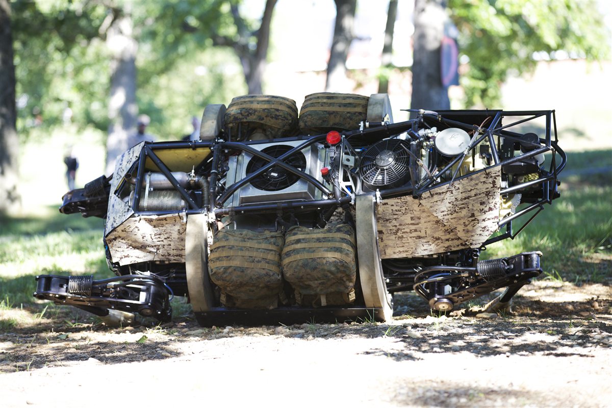
BigDog (2005). The modern era of quadruped robots traces its origin to BigDog, a DARPA-funded hydraulic quadruped built by Boston Dynamics with Foster-Miller, the NASA Jet Propulsion Laboratory, and the Harvard University Concord Field Station [1]. First publicly demonstrated in 2005, BigDog weighed 240 lb (110 kg), stood 2.5 ft (0.76 m) tall, and could traverse slopes up to 35°, carry 340 lb, and run at 4 mph [1]. Its legs were hydraulically actuated with four actuated degrees of freedom per leg — two at the hip, one at the knee, one at the ankle — and driven by an onboard gasoline engine [1]. The engine noise proved to be the platform’s critical failing: it could be heard from hundreds of meters away, making it unsuitable for the infantry support mission DARPA intended, and the project was discontinued around 2013 [1]. The Legged Squad Support System (LS3), BigDog’s direct successor, demonstrated in September 2012, followed the same hydraulic, quadruped-mule concept before being shelved for the same reason [1].
LittleDog and the learning-locomotion era. Alongside BigDog, DARPA funded a second platform called LittleDog — a smaller quadruped explicitly designed for locomotion-learning research, not load carriage. LittleDog ran from roughly 2005 to 2009 as a benchmark platform shared across research groups, producing foundational work on motion planning and learned gaits that still appears as a baseline in academic papers [16].
MIT Cheetah (2009–present). The decisive shift away from heavy hydraulics toward high-performance electric actuation came from Sangbae Kim’s Biomimetic Robotics Lab at MIT, established around 2009 [2]. The lab’s guiding insight was that a cheetah’s speed comes less from powerful muscles than from efficient energy transfer through leg tendons and a compliant spine — an insight that translated into the design principle of lightweight, backdrivable, proprioceptive electric actuation rather than high-gear-ratio servos. The first Cheetah prototype was demonstrated publicly around 2012, with a paper on design principles published in 2013. Cheetah 3 (2018) extended this approach to all three degrees of freedom per leg, giving each joint identical backdrivable motor modules and enabling fully three-dimensional proprioceptive force control [3]. The MIT Mini Cheetah (2019), led by Benjamin Katz with Sangbae Kim, carried the paradigm into a compact, repairable 9 kg (20 lb) platform: 12 identical motor modules each with a 6:1 gear reduction, arranged three per leg for 12 total actuated degrees of freedom [4][5]. The Mini Cheetah demonstrated a 360° backflip and was the direct inspiration for a generation of open-source and commercial quadrupeds [4]. The actuator design underlying the MIT Cheetah series is examined in the actuation paradigms section below.
ANYmal and ANYbotics (2016). Independent of the MIT lineage, the Robotic Systems Lab at ETH Zurich developed ANYmal, a quadruped built around series-elastic actuators rather than quasi-direct-drive motors. ANYbotics was founded in 2016 as an ETH Zurich spin-off by Péter Fankhauser, Marco Hutter, and Hannes Sommer [6], with first commercial sales in 2017 [6]. ANYmal targeted industrial inspection — oil and gas platforms, chemical plants, mines — where robustness, certifiability, and explicit force sensing matter more than raw agility. The platform has since been deployed in those environments at scale and continues to represent the series-elastic design school, a counterpoint to the MIT proprioceptive approach. Both paradigms are competitive; both appear in the current commercial market.
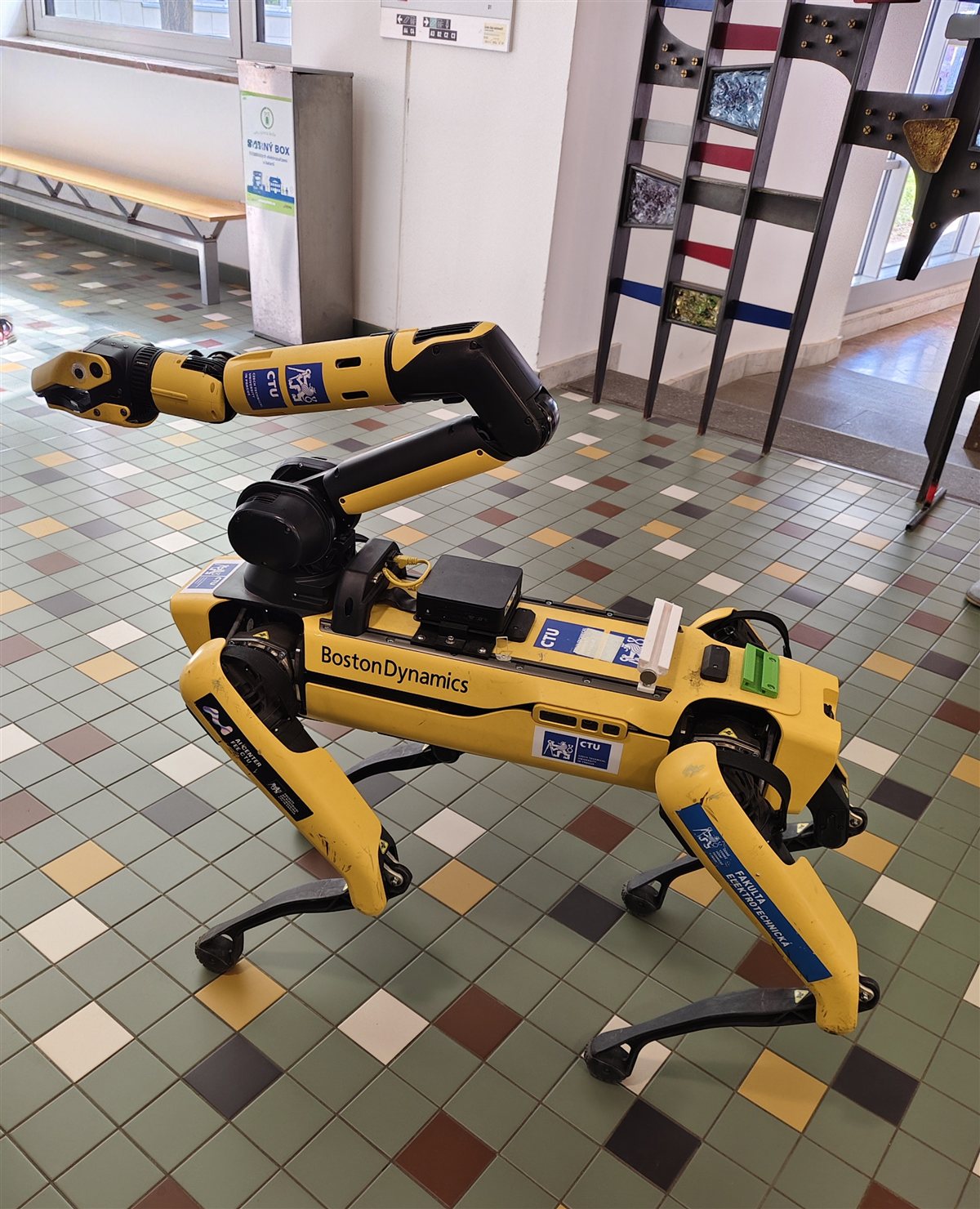
Boston Dynamics Spot (commercial launch June 2020). Boston Dynamics had been developing the SpotMini platform from roughly 2016, making it available for lease under an Early Adopter Program that placed over 150 units [7][8]. On 2020-06-16, commercial sales opened to any U.S. business at a base price of $74,500 [7][8]. This date marks the first time a quadruped robot reached general commercial availability, not restricted to government or academic channels. Spot runs electric actuators (not publicly characterized as QDD or SEA in official documentation, though its low-inertia, backdrivable behavior is consistent with the proprioceptive approach), weighs approximately 32.5 kg [17], and is routinely deployed in security patrol, construction site inspection, and industrial monitoring.
Unitree and the consumer tier (2020–2021). While Spot established the professional market, Unitree Robotics in China drove prices down by an order of magnitude. The Unitree A1 became available around 2020, followed in 2021 by the Go1 at a launch price of $2,700 for the base model — described by IEEE Spectrum as the first consumer-priced quadruped robot [9]. The Go1 line runs quasi-direct-drive electric actuators, a direct descendant of the MIT Mini Cheetah actuation philosophy, and offers an API-accessible Edu version aimed at researchers and hackers. Unitree has since released the B1, B2, and GO2, progressively improving torque, weatherproofing, and compute at prices still far below Spot.
The DIY era. The convergence of open-source control software (Cheetah-software from MIT, ODrive motor controllers), affordable brushless motors, FDM 3D printing, and platforms like the Stanford Pupper and SpotMicro created an active community of home builders by 2020–2022. The Stanford Pupper, a 12-DOF 3D-printed quadruped designed specifically for the educational market, and the MIT Mini Cheetah’s open-sourced hardware design inspired dozens of derivative builds, bringing legged robotics within reach of a machinist or engineer with a modest budget and a serious shop. The RoboDog project sits in this lineage: informed by the research that produced Spot and ANYmal, building at the scale that the open-source community has made tractable.
2.2 Why four legs
The mission that drives RoboDog — outdoor patrol on a residential property in Michigan, including lawn, gravel, stairs, and snow-covered slopes — is a terrain problem. Terrain that defeats a wheeled platform does not defeat a legged one, because a legged robot negotiates obstacles by choosing where each foot lands rather than rolling over them continuously [10].
The terrain argument. Wheels are efficient on flat continuous surfaces and mechanically simple, but cannot climb a stair tread cleanly, negotiate a frost-heaved concrete seam, or push through snow without the wheel sinking. Tracks improve on wheels for loose ground but still cannot step over obstacles cleanly and are mechanically complex to IP-seal for wet operation. Legged systems step — each foot placement is a discrete, controlled event — which is the fundamental advantage on discontinuous, uneven terrain.
Why four legs specifically. Among legged configurations, quadrupeds occupy the practical middle of the design space:
- Bipeds require constant active balance at all speeds, including when standing still, and have high fall risk on uneven ground. Recovery from a fall is a research problem in itself. The control problem is harder and the mechanical margins are smaller.
- Hexapods and beyond carry more actuators and more mechanical complexity than the mission demands, and designing one from scratch in a private shop is substantially more work. Their main advantage — redundancy of ground contact — is meaningful for very rough terrain but not a deciding factor at residential-property scale.
- Quadrupeds offer four contact points, a well-understood range of static and dynamic gaits, a mature ecosystem of reference designs and open-source software, and a body plan that can achieve static stability — standing without active balance computation — in slow gaits.
Static stability. A legged robot is statically stable when the vertical projection of its center of mass (CoM) onto the ground plane lies within the support polygon — the convex hull of its current foot contact points [11]. For a quadruped with all four feet on the ground, the support polygon is a quadrilateral; the robot can stand without active balance computation as long as the CoM stays inside it. During a static gait, the robot maintains at least three feet on the ground at every instant, ensuring that the support polygon is always a triangle [11]. The minimum distance from the CoM projection to any edge of the support polygon is the stability margin; higher margins mean more robustness to perturbations.
Dynamic stability. Static stability is sufficient for slow, deliberate gaits, but the faster and more agile gaits the RoboDog program ultimately targets — trotting at speed, recovering from a push — require dynamic stability. A dynamically stable gait is one in which the robot uses momentum and inertia to maintain balance even during phases when fewer than three feet are on the ground, or when the CoM is momentarily outside the support polygon. Dynamic stability is the domain of model-predictive control and whole-body control, discussed in the kinematics and dynamics section below.
2.3 Anatomy of a robot dog
A quadruped robot is built around a rigid or semi-rigid body — the spine or chassis — from which four legs extend. The body houses the compute, power, and communications hardware. Each leg attaches to the body at a hip mount and consists of two rigid links (thigh and shank) connected by three revolute joints.
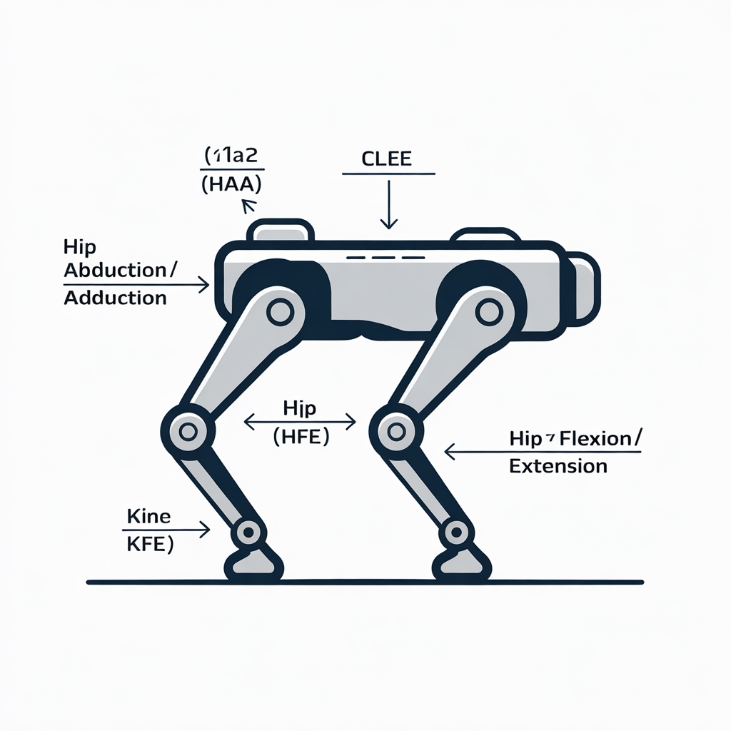
The three-joint leg. The canonical modern quadruped leg — used in the MIT Mini Cheetah, ANYmal, Spot, Unitree A1/Go1, and the designs in this survey — has three revolute joints [4][12]:
-
Hip Abduction/Adduction (HAA) — the outermost joint, mounted on the hip shoulder. It rotates the leg sideways, outward or inward relative to the body. Abduction swings the leg away from the body; adduction draws it back in. This joint is what allows the robot to strafe laterally or adjust its foot placement left and right without rotating the whole body.
-
Hip Flexion/Extension (HFE) — the joint between the hip shoulder and the upper thigh link. It swings the leg forward (flexion) and backward (extension) relative to the body — the equivalent of the hip joint in a quadruped animal. This is the primary joint for stride length and walking speed.
-
Knee Flexion/Extension (KFE) — the joint between the thigh (upper link) and shank (lower link), equivalent to a quadruped’s knee. Flexion draws the foot upward toward the body; extension reaches the foot down toward the ground.
The shank terminates in a foot — typically a rubber-tipped pin in research robots, a spherical rubber foot in commercial platforms. Some designs add a passive ankle (a compliant spring rather than an actuated joint) to soften foot impact, but the foot is not the fourth actuated degree of freedom that BigDog’s hydraulic ankle was.
Twelve degrees of freedom. Three actuated joints per leg, four legs: 12 total actuated degrees of freedom [4][12]. This number comes up repeatedly in quadruped robotics literature because it is the minimum that enables a full repertoire of gaits — walk, trot, bound, gallop — and arbitrary foot placement in three-dimensional space. The 12-DOF count is for the actuated joints only; the floating base (the body) adds 6 unactuated degrees of freedom (three translation, three rotation), giving the full robot 18 DOF to reason about in whole-body control.
Link geometry matters. The lengths of the thigh (L1) and shank (L2) determine the robot’s reachable workspace and strongly influence torque requirements at each joint. Longer legs extend the workspace and reduce the number of steps per meter but increase the moment arm that the hip actuators must fight. Shorter legs reduce that moment arm but shrink the workspace and limit stride height, which matters for stair-climbing. For a Labrador-scale robot with a 20–24 in shoulder height, leg geometry and actuator torque budgets interact closely — a relationship the build volumes (Vols 5–7) address explicitly once actual actuator candidates are selected.
2.4 Gaits
A gait is the repeating pattern of foot contacts that a legged robot uses to move. Gaits are characterized by which feet are on the ground, when, and for how long — the support pattern — and whether the gait is static (CoM always inside the support polygon) or dynamic (momentum and inertia carry the robot through phases of reduced support).
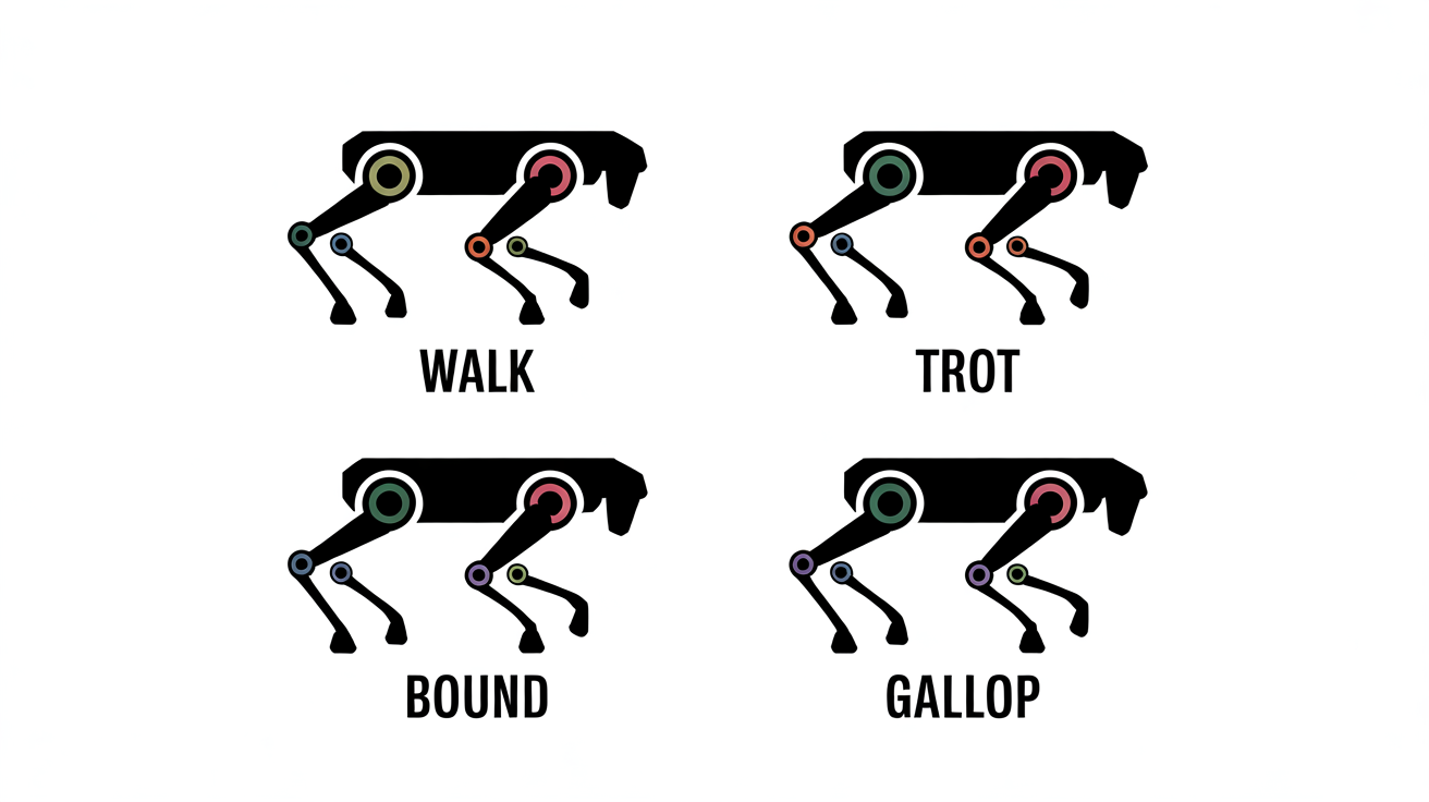
Walk. The walk is the canonical static gait for quadrupeds. At any instant, at least three feet are on the ground (typically all four at slow speeds, with one foot lifting at a time). The CoM projection always lies within the support triangle or quadrilateral. Walks are stable at arbitrarily slow speeds, including zero — the robot can pause mid-stride without falling. The tradeoff is low speed and high computational simplicity: deciding which foot to move next and where to place it can be done with a straightforward planner rather than a full dynamics model.
Trot. The trot moves diagonal pairs of legs in phase: front-left and rear-right swing together, then front-right and rear-left swing together. At low trotting speeds, a brief four-foot double-support phase keeps the CoM in the support polygon (quasi-static trot). At higher speeds, the double-support phase disappears and the robot briefly has only two feet — a diagonal — on the ground, requiring dynamic balance. The trot is the workhorse gait for research quadrupeds: it is fast, energy-efficient at moderate speeds, and stable enough for outdoor terrain. The MIT Mini Cheetah’s maximum demonstrated trot speed is 3.84 m/s [4]; Spot operates at roughly 1.6 m/s nominal [17].
Bound. The bound groups the front pair (front-left + front-right) and the rear pair (rear-left + rear-right) together, alternating between them. The torso pitches noticeably, and there are brief flight phases between the two pair contacts. Bound is faster than trot for a given leg configuration and is the gait used by many mid-speed running animals. It is feasible in robot implementations (MIT Mini Cheetah has demonstrated bounding) but requires active pitch stabilization.
Gallop. The gallop adds an extended aerial phase — all four feet off the ground simultaneously — between the front-pair and rear-pair contacts, and may further stagger the individual feet within each pair. It is the fastest quadruped gait. The gallop places extreme demands on the control system: the robot must predict landing forces and joint torques well ahead of contact, since passive stability is impossible during the aerial phase. Full galloping gaits in robots remain a research demonstration rather than a routine operational mode, though the MIT Cheetah 3 demonstrated running and jumping over obstacles [3].
Static vs dynamic: a practical line. For the RoboDog program, the operating-envelope requirement (rough terrain, stairs, outdoor patrol) means the robot needs at least a capable dynamic trot by Build 2. Build 1 (FDM, hobby servos) is unlikely to achieve a stable high-speed trot and should be considered successful if it can execute a reliable slow walk on flat surfaces. Build 3’s target for unattended outdoor patrol requires a dynamic trot — the gait Spot uses for its autonomous security missions.
2.5 Kinematics and dynamics basics
Control of a quadruped robot reduces to two related problems: knowing where the feet are given the joint angles (forward kinematics), choosing the joint angles that put the feet where they need to be (inverse kinematics), and choosing the joint torques that keep the whole robot in balance while doing so (dynamics and control).
Forward kinematics (FK). Given the joint angles — three angles per leg, one per actuated joint — the forward kinematics map computes the Cartesian position and orientation of each foot in the robot’s body frame. For a three-joint leg with known link lengths L1 (thigh) and L2 (shank) and known joint axes, FK is a straightforward chain of rotation matrices (Denavit-Hartenberg or similar). FK is computationally cheap and runs continuously in the control loop to maintain an estimate of foot position.
Inverse kinematics (IK). Given a desired foot position, IK computes the joint angles that achieve it. For a 3-DOF leg with two links and standard joint geometry, a closed-form geometric solution exists — the leg is a 2R manipulator in the sagittal plane, preceded by an abduction rotation [13]. No iterative numerical solver is required for the standard leg geometry, which makes IK fast enough to run at control-loop frequencies (500–1000 Hz in research systems [18]). The existence of the closed-form solution is one reason the 3-DOF, two-link leg geometry has become standard: it is both physically capable and analytically tractable.
Zero Moment Point (ZMP). The ZMP, introduced by Vukobratović and Juričić in 1969 [14], is the point on the ground where the net ground reaction force acts — equivalently, the point at which the reaction forces produce no net moment about the horizontal axes. If the ZMP lies within the support polygon, the robot is dynamically stable (no net tipping moment); if it moves outside the polygon, the robot will rotate about the polygon’s edge — it will fall. ZMP-based control was the dominant gait-planning approach for bipeds (Honda ASIMO, Sony QRIO) and early quadrupeds, and remains a useful stability check even in more sophisticated modern controllers.
Model Predictive Control (MPC). Modern high-speed quadrupeds — MIT Mini Cheetah, ANYmal, Spot — use MPC rather than ZMP planning as their primary locomotion controller. An MPC controller models the robot’s dynamics over a short future horizon (typically 0.5–1.5 s), predicts the consequences of candidate control actions, and selects the sequence that minimizes a cost function (staying on trajectory, minimizing contact forces, tracking body height). The solution is recomputed at every control cycle, so the robot continuously adapts its plan as the terrain changes under its feet [3][5]. MPC controllers are computationally expensive — Spot-class robots run dedicated onboard compute for locomotion control — but they enable robust trotting and recovery from pushes that ZMP-only approaches could not handle.
Whole-body control (WBC). Whole-body control extends MPC with a hierarchical task framework [3]. Instead of planning foot forces independently of body orientation, WBC reasons simultaneously about all 18 DOF of the floating-base robot (12 actuated joints + 6 body DOF) and distributes torques across all joints to satisfy a prioritized list of tasks: (1) maintain balance and support polygon, (2) track a desired body trajectory, (3) track desired swing-foot trajectories, (4) minimize energy. The priority ordering ensures that a higher-priority task is never sacrificed for a lower one. WBC is the control architecture of Cheetah 3 [3] and is increasingly common in research quadrupeds as compute power sufficient to solve the optimization in real time has become available on embedded platforms. Vol 8 (the autonomy and vision stack) addresses how the locomotion controller fits into the broader ROS 2 / Nav2 software architecture.
2.6 Actuation paradigms
The choice of actuator is the single most consequential design decision in a quadruped build. Three paradigms dominate the current landscape. Actuator choices for the RoboDog build ladder are surveyed in detail in Vol 4; this section defines the paradigms so that the terminology is clear.
Geared servo. A geared servo couples an electric motor to the output joint through a high-ratio gearbox — typically 50:1 to 300:1 [19] — followed by a position sensor (encoder or potentiometer). The high gear ratio multiplies motor torque substantially, which is why inexpensive brushless hobby motors can move a robot’s leg. The cost is reflected inertia: the gear ratio squares when converting motor inertia to the output side, making the joint mechanically stiff to impacts and unable to feel external forces through the drive train. High-ratio servos are not backdrivable — an external force at the foot does not move the motor; instead, the gearbox absorbs or shatters. In practice, hobby servos in quadruped builds absorb repeated foot-impact forces by slowly stripping gears. Geared servos are cheap, widely available, and adequate for Build 1’s teleoperated flat-surface walking, but they impose a hard ceiling on speed, agility, and terrain robustness.
Quasi-direct-drive (QDD) / proprioceptive actuation. QDD motors use a low gear ratio — typically 6:1 to 10:1 [4][5] — to retain most of the motor’s natural backdrivability. At these ratios, a force at the foot can be measured through the motor’s current draw without a dedicated force sensor: current is proportional to torque, and with the gear ratio and link geometry known, the controller can estimate foot contact force from motor current alone. This is the proprioceptive sensing that Wensing et al. describe in the MIT Cheetah proprioceptive actuation paper [5]: “proprioceptive actuation uses collocated force control at the joints to effectively control contact interactions at the feet under dynamic conditions” and “combines high torque density, high-bandwidth force control, and impact mitigation via backdrivability” [5]. The backdrivability also means a foot impact — hitting a rock or a stair edge — compresses the joint briefly rather than shattering a gearbox. MIT Mini Cheetah’s 6:1 modules achieved impact times of 85 ms and peak forces over 450 N [5]. The Unitree A1/Go1/Go2 all use QDD motors descended from this lineage. Build 2 of the RoboDog program targets QDD actuators.
Series-elastic actuator (SEA). Pratt and Williamson introduced the series-elastic actuator in 1995 [15], placing a calibrated compliance (a spring) in series between the motor–gearbox output and the joint output. The spring deformation is measured directly, giving an explicit and accurate force measurement independent of gear-train friction or motor current estimation. SEAs tolerate impacts by compressing the spring rather than transmitting the impulse to the gearbox, and they can store and release energy during a step cycle. ANYmal’s ANYdrive actuators are SEAs. The tradeoff relative to QDD is bandwidth: a spring in the load path limits the rate at which force can change, which can restrict gait agility and top speed. SEAs also add mechanical complexity (spring, deflection sensor) to each actuator. For industrial-inspection applications where force accuracy, certifiable safety, and impact tolerance matter more than top speed, the SEA paradigm remains competitive. Vol 4 compares specific QDD and SEA candidates with performance numbers relevant to the RoboDog build tiers.
2.7 Terminology reference
The following definitions are used consistently throughout the RoboDog survey volumes.
Table 1 — Terminology reference
| Term | Definition |
|---|---|
| DOF | Degree of freedom — one independent axis of motion. A revolute joint is one DOF. |
| HAA | Hip Abduction/Adduction — the leg joint that swings the leg laterally. |
| HFE | Hip Flexion/Extension — the leg joint that swings the leg fore and aft. |
| KFE | Knee Flexion/Extension — the leg joint that extends or retracts the shank. |
| Thigh (upper link) | The rigid link between the HFE and KFE joints. |
| Shank (lower link) | The rigid link between the KFE joint and the foot. |
| Support polygon | The convex hull of the current foot contact points projected to the ground plane. |
| CoM | Center of mass — the mass-weighted average position of all the robot’s mass. |
| ZMP | Zero Moment Point — the ground point where the net ground reaction force produces no horizontal moment. Must lie within the support polygon for stable motion. |
| FK | Forward kinematics — computing foot position from joint angles. |
| IK | Inverse kinematics — computing joint angles from a desired foot position. |
| MPC | Model Predictive Control — predicting and optimizing control actions over a future time horizon. |
| WBC | Whole-body control — hierarchical torque control of all robot DOF simultaneously. |
| QDD | Quasi-direct-drive — a low-gear-ratio motor arrangement that retains backdrivability and proprioceptive force sensing. |
| SEA | Series-elastic actuator — an actuator with a compliant spring in series, enabling direct force measurement and impact tolerance. |
| Proprioceptive sensing | Force/torque estimation through actuator current and position sensing, without a dedicated external force sensor. |
| Backdrivable | A joint or actuator is backdrivable if an external force at the output can move the motor input — the opposite of a worm-gear or high-ratio servo. |
| Trot | A diagonal-pair gait: FL+RR and FR+RL alternate. |
| Bound | A front-rear-pair gait: both front legs then both rear legs, with brief flight phases. |
| Gallop | The fastest quadruped gait, with extended aerial phases between foot-pair contacts. |
| Floating base | The 6-DOF body of the robot, which is not directly actuated — balance is achieved indirectly through the leg joints. |
| SLAM | Simultaneous Localization and Mapping — building a map while tracking the robot’s position in it. Used in Build 2/3 autonomy. |
| Swing phase | The portion of a gait cycle when a foot is off the ground, moving to its next contact point. |
| Stance phase | The portion of a gait cycle when a foot is on the ground, supporting the body. |
Sources
-
Wikipedia contributors. “BigDog.” Wikipedia, The Free Encyclopedia — history, dates, DARPA funding, specifications, discontinuation (accessed 2026-06-18). https://en.wikipedia.org/wiki/BigDog
-
MIT Technology Review. “Forces of Nature” — Sangbae Kim, MIT Biomimetics Robotics Lab founding and MIT Cheetah design philosophy (accessed 2026-06-18). https://www.technologyreview.com/2018/12/19/138516/forces-of-nature/
-
Bledt, G., Powell, M. J., Katz, B., Di Carlo, J., Wensing, P. M., Kim, S. “MIT Cheetah 3: Design and Control of a Robust, Dynamic Quadruped Robot.” 2018 IEEE/RSJ International Conference on Intelligent Robots and Systems (IROS). MIT Open Access — 3-DOF per leg with proprioceptive actuation on all joints, whole-body control, MPC (accessed 2026-06-18). https://dspace.mit.edu/handle/1721.1/126619
-
MIT Robotics. “Mini Cheetah is the first four-legged robot to do a backflip” — 3 DOF per leg, 12 total actuated DOF, 9 kg weight, 6:1 gear reduction, 3.84 m/s trot speed (accessed 2026-06-18). https://robotics.mit.edu/mini-cheetah-first-four-legged-robot-do-backflip/
-
Wensing, P. M., Wang, A., Seok, S., Otten, D., Lang, J., Kim, S. “Proprioceptive Actuator Design in the MIT Cheetah: Impact Mitigation and High-Bandwidth Physical Interaction for Dynamic Legged Robots.” IEEE Transactions on Mechatronics, 2017 — proprioceptive/QDD actuation: collocated force control, backdrivability, high-bandwidth, 85 ms impact time, >450 N peak force (accessed 2026-06-18). https://www.semanticscholar.org/paper/Proprioceptive-Actuator-Design-in-the-MIT-Cheetah:-Wensing-Wang/793f0a0c2ee71d20f719557ab5d90636963f62a1
-
Wikipedia contributors. “ANYbotics.” Wikipedia, The Free Encyclopedia — founding in 2016 as ETH Zurich spin-off, founders, industrial inspection applications; first commercial sales 2017 (accessed 2026-06-18). https://en.wikipedia.org/wiki/ANYbotics
-
TechCrunch. “Now any US business can buy Boston Dynamics’ Spot robot for $74,500,” 2020-06-16 — first general commercial sales of Spot, base price $74,500 (accessed 2026-06-18). https://techcrunch.com/2020/06/16/now-any-us-business-can-buy-boston-dynamics-spot-robot-for-74500/
-
Boston Dynamics. “Commercial Sales of Spot Robot Launch” — official news announcement, June 2020, confirming the launch date and Early Adopter Program history (accessed 2026-06-18). https://bostondynamics.com/news/boston-dynamics-launches-commercial-sales-of-spot-robot/
-
IEEE Spectrum. “Unitree’s Go1 Robot Dog Looks Pretty Great, Costs Just $2,700” — Go1 launch 2021, first consumer-priced quadruped (accessed 2026-06-18). https://spectrum.ieee.org/unitrees-go1-robot-dog-looks-pretty-great-costs-just-usd-2700
-
Margolis, G. et al. “Reinforcement Learning for Blind Stair Climbing with Legged and Wheeled-Legged Robots.” arXiv:2402.06143v1 — wheeled robots lack stair agility; legged systems choose foot placement (accessed 2026-06-18). https://arxiv.org/html/2402.06143v1
-
Zheng, Y. et al. “Stability-Guaranteed and High Terrain Adaptability Static Gait for Quadruped Robots.” PMC7506578, Sensors, 2020 — support polygon definition, ≥3 feet for static stability, stability margin (accessed 2026-06-18). https://pmc.ncbi.nlm.nih.gov/articles/PMC7506578/
-
Cornell ECE 4760 Project, Fall 2025 (Broderick, Liou). “12-DOF Quadruped Robot with Environmental Mapping” — 12 servo motors, 3 per leg (hip yaw, hip pitch, knee), standard 12-DOF architecture corroborated (accessed 2026-06-18). https://ece4760.github.io/Projects/Fall2025/seb353_cjl298/index.html
-
Oscarliang. “Quadruped Robot Gait Study” — closed-form IK for 3-DOF leg, gait taxonomy (walk, trot, bound, gallop), support polygon analysis (accessed 2026-06-18). https://oscarliang.com/quadruped-robot-gait-study/
-
Vukobratović, M., Borovac, B. “Zero-Moment Point — Thirty Five Years of its Life.” International Journal of Humanoid Robotics, 2004 — ZMP originally defined by Vukobratović & Juričić (1969); stability criterion for legged robots (accessed 2026-06-18). https://www.semanticscholar.org/paper/Zero-Moment-Point-Thirty-Five-Years-of-its-Life-Vukobratovic-Borovac/3f9b39a746e67f8f45427f738139f0ee343ebc0c
-
Pratt, G., Williamson, M. “Series Elastic Actuators.” Proceedings of the 1995 IEEE/RSJ International Conference on Intelligent Robots and Systems (IROS), Vol. 1, pp. 399–406 — SEA concept: spring in series for force control, impact tolerance, low mechanical impedance, energy storage; the originating paper that introduced the SEA paradigm (accessed 2026-06-18). https://www.semanticscholar.org/paper/Series-elastic-actuators-Pratt-Williamson/e99eda93c1090c606800064f7d904fa006e64332
-
Kolter, J. Z., Ng, A. Y. “The Stanford LittleDog: A Learning and Rapid Replanning Approach to Quadruped Locomotion.” International Journal of Robotics Research, 30(2), pp. 150–174, 2011 — DARPA Learning Locomotion program benchmark paper; LittleDog as shared research platform used by six teams, 2005–2009 (accessed 2026-06-18). https://journals.sagepub.com/doi/abs/10.1177/0278364910390537
-
Boston Dynamics. “Spot Specifications” — official specification sheet: net weight 32.5 kg, maximum speed 1.6 m/s (accessed 2026-06-18). https://www.bostondynamics.com/sites/default/files/inline-files/spot-specifications.pdf
-
Katz, B., Di Carlo, J., Kim, S. “Mini Cheetah: A Platform for Pushing the Limits of Dynamic Quadruped Control.” 2019 IEEE International Conference on Robotics and Automation (ICRA), pp. 6295–6301 — MIT Mini Cheetah platform; main control loop at approximately 500 Hz; QDD actuators with 6:1 planetary gear reduction (accessed 2026-06-18). https://www.semanticscholar.org/paper/Mini-Cheetah:-A-Platform-for-Pushing-the-Limits-of-Katz-Carlo/bb7e50d5d25ebf46f04c6d8cabdaac72a0e9d297
-
ROBOTIS. “Dynamixel AX-12A” — servo motor specification: gear ratio 254:1; representative of high-ratio geared servo actuators widely used in hobby and research robotics platforms (accessed 2026-06-18). https://emanual.robotis.com/docs/en/dxl/ax/ax-12a/